←→ move between slides · F full screen · M slide list
Before we start
Why this matters
What do a light switch, a calculator, and the robot vacuum currently stuck under your sofa have in common?
All three are having exactly one conversation, forever: yes or no. No maybes, no “let me think about it”, no vibes. Over the next 13 chapters you'll watch that painfully simple conversation, repeated a few billion times, somehow add up to a phone that can beat you at chess and still not know where your keys are.
Outline
Topics in this chapter
Select a topic to jump to the slide that explains it.
Digital logic design is the craft of building systems that represent information with a small set of discrete values, almost always 0 and 1, and then process, store and move that information. A phone, a calculator and a CPU are built from the same ingredients: logic gates, storage elements and a clock.
This course climbs a ladder. You start with single gates, add arithmetic circuits and data selectors, then memory, counters and finite state machines, and finish with the datapath of a small computer.
An analog signal changes continuously and can take any value in a range. Noise shifts the value and nothing in the signal tells you it happened. A digital signal uses ranges: any voltage below a low threshold reads as logic 0 (LOW), and any voltage above a high threshold reads as logic 1 (HIGH). Small noise leaves the decoded bit unchanged.
Reliability and noise tolerance
Easy storage and copying
Easy processing and programmability
Repeatability: the same input always gives the same output
Concept 3 of 5
Bits, bytes and truth tables
One binary digit is a bit. Eight bits make a byte. n bits give 2n different patterns, and those patterns can stand for numbers, characters, instructions or control signals.
The basic operations are AND, OR and NOT. A truth table lists every input combination and the output for each. A function of n inputs has 2n rows.
A byte drawn as 8 bit boxes, most significant bit (MSB) on the left down to least significant bit (LSB) on the right. Each box shows its binary place value, from 128 down to 1.
A byte is 8 bits, and computers count naturally in powers of two — so storage sizes are rounded to the nearest convenient power of two instead of an exact power of ten. Each step up multiplies by 210 = 1024, not by 1000.
Each step is still just 1024 times the last one — a typical laptop drive is measured in GB or TB today, while PB and EB are the scale data centres and cloud-storage providers deal in (Google and Facebook each store several EB of data). That's also why a drive advertised as “500 GB” shows up as less in your file explorer: storage manufacturers use the decimal definition (1 KB = 1000 bytes exactly, the SI prefix), while operating systems usually report the binary value above. The unambiguous binary names are KiB, MiB, GiB, TiB, PiB and EiB (kibi-, mebi-, gibi-, tebi-, pebi-, exbi-byte) — but “KB/MB/GB/TB” gets used loosely for both in everyday speech, which is exactly where the confusion comes from.
Concept 5 of 5
From transistors to computers
Transistor›Logic gate›Circuit›Module›CPU›Computer
Each level is built only from the level to its left.
A combinational circuit produces outputs that depend only on its present inputs. A sequential circuit also depends on stored state, so it needs memory elements and usually a clock.
See this flow inside a real computer
Inside the Computer is an interactive diagram of a desktop PC — click the case, the CPU, RAM and more to see how each level of this chain sits physically inside the box.
Open Inside the ComputerInside the ComputerAn interactive diagram of a desktop PC — click any part, from the case down to the CPU and RAM, to see what it does.
How many rows does the truth table of a 5-input function have?
Show the solution
Each input doubles the number of combinations.
Rows = 25 = 32.
Worked example 2 of 2
Worked example 2
How many values can one byte hold, and what is the largest unsigned value?
Show the solution
8 bits give 28 = 256 patterns.
Counting from 0, the largest is 256 − 1 = 255.
Practice
Practice (1 of 2)
Try each one on paper first, then check your answer.
1. Classify each as combinational or sequential: a 4-bit adder, a counter, a decoder, a register.
Show the answer
Adder and decoder are combinational. Counter and register are sequential because they store state.
2. Write the truth table of a 2-input AND gate.
Show the answer
00 → 0, 01 → 0, 10 → 0, 11 → 1.
3. Give two reasons digital systems tolerate noise better than analog ones.
Show the answer
Signals are read against thresholds, so small deviations decode to the same bit, and a noisy signal can be regenerated to clean levels.
Practice
Practice (2 of 2)
Try each one on paper first, then check your answer.
4. How many bits are needed to label 100 different items?
Show the answer
7 bits, because 26 = 64 is too small and 27 = 128 is enough.
Practice in Gate Forge
Place switches, gates and LEDs, then use the Truth table tester to see every input combination.
Open Gate ForgeGate ForgeA free circuit simulator — place and wire gates, generate truth tables and timing diagrams, and work through 90+ guided problems.
Check yourself
Quiz
Summary
Summary
Digital systems process discrete values, usually 0 and 1.
A bit is one binary digit and a byte is 8 bits. n bits give 2n patterns.
AND, OR and NOT are the basic operations. A truth table lists all 2n input combinations.
Combinational output depends on present inputs only. Sequential output also depends on stored state.

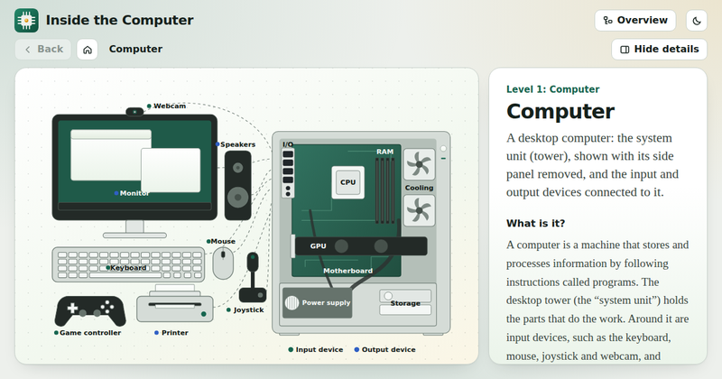 Inside the ComputerAn interactive diagram of a desktop PC — click any part, from the case down to the CPU and RAM, to see what it does.
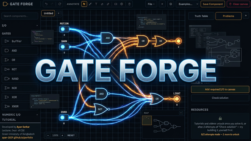 Gate ForgeA free circuit simulator — place and wire gates, generate truth tables and timing diagrams, and work through 90+ guided problems.