
Topic 13 of 13
Digital Systems & Practice
Put the blocks together: a small ALU, a traffic light, a digital lock, and design workflows.
← → move between slides · F full screen · M slide list
Before we start
Why this matters
You've now built gates, memory, counters and state machines one lonely piece at a time — so what happens when you finally let them all hang out in the same box?
A digital lock that never forgets its combination (unlike you, probably). A traffic light that will never show green in both directions and start a demolition derby. A tiny ALU that adds and compares like a miniature CPU running on too much coffee. This closing chapter is the reunion episode.
Outline
Topics in this chapter
Select a topic to jump to the slide that explains it.
- Digital system building blocks
- Complete combinational design workflow
- Complete sequential design workflow
- CPU: ALU, registers, control unit, memory, buses
- 4-bit ALU
- Traffic light controller
- Digital lock
- Vending machine
- Digital clock
- Troubleshooting
- Logic Bench
- Practice projects
- 3×3 multiplier
- 101 sequence detector
- MOD-6 counter
- Mini digital system
- Comprehensive review
- Viva questions
- Final project
Concept 1 of 4
Building blocks and workflows
Combinational workflow: specification → truth table → Boolean expression → K-map → implementation → verification.
Sequential workflow: identify states → state diagram → state table → state assignment → choose flip-flops → equations → implement and verify.
Concept 2 of 4
Inside a CPU
A CPU has a datapath (registers, ALU, buses) and a control unit. The control unit is a finite state machine that decodes instructions and coordinates the datapath. The CPU talks to memory over an address bus, a data bus and a control bus. A 4-bit ALU combines an adder-subtractor and logic gates, with select lines that choose the result through multiplexers.
Concept 2 of 4
Inside a CPU (cont.)
Concept 3 of 4
Example systems
- Traffic light: an FSM with states for each light combination and a counter that times each state.
- Digital lock: an FSM that tracks a button sequence and unlocks when the correct one is detected.
- Vending machine: states record accumulated credit, inputs are coins, outputs release product or change.
- Digital clock: counters divide the clock frequency, registers hold digits, decoders drive displays.
Concept 4 of 4
Troubleshooting checklist
- Clock assumptions: edge, frequency, is it running?
- Input values and switch positions.
- Truth table or state table against the circuit.
- Gate connections and pin numbers.
- Reset and initial state.
- Timing: setup, hold, and every state transition.
Truth tables
Truth tables (1 of 2)
4-bit ALU functions
| Op code | Operation |
|---|---|
| 000 | A + B |
| 001 | A − B |
| 010 | A AND B |
| 011 | A OR B |
| 100 | A XOR B |
| 101 | NOT A |
| 110 | A + 1 |
| 111 | Pass B |
Traffic light controller
| State AB | North–South | East–West | Ticks |
|---|---|---|---|
| 00 | Green | Red | 4 |
| 01 | Yellow | Red | 2 |
| 10 | Red | Green | 4 |
| 11 | Red | Yellow | 2 |
Truth tables
Truth tables (2 of 2)
Digital lock for code 1011
| State | Input 0 → next | Input 1 → next |
|---|---|---|
| 0 | 0 | 1 |
| 1 | 2 | 1 |
| 2 | 0 | 3 |
| 3 | 2 | 4 |
| 4 (unlocked) | 0 | 1 |
State k means the first k digits of the code have been matched.
Interactive
Demo: ALU, traffic light and lock
Worked example 1 of 2
Worked example 1
Show the solution
- Each of the 3 bits of B multiplies each of the 3 bits of A.
- 3 × 3 = 9 AND gates.
- Adders then sum the shifted rows into a 6-bit product.
Worked example 2 of 2
Worked example 2
Show the solution
- Four states (NS green, NS yellow, EW green, EW yellow).
- ⌈log₂4⌉ = 2 flip-flops, plus a counter for timing.
Practice
Practice (1 of 2)
Try each one on paper first, then check your answer.
Show the answer
Show the answer
Show the answer
Practice
Practice (2 of 2)
Try each one on paper first, then check your answer.
Show the answer
Combine an adder, a multiplexer and flip-flops into a tiny ALU, and Save the parts as components.
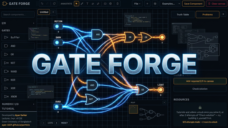 Gate ForgeA free circuit simulator — place and wire gates, generate truth tables and timing diagrams, and work through 90+ guided problems.
Check yourself
Quiz
Summary
Summary
- Complex systems are built by combining simple blocks.
- A CPU is a datapath plus a control unit connected to memory by buses.
- FSMs make controllers such as traffic lights and locks.
- Follow the workflow: specify, model, simplify, implement, verify.
- Troubleshoot clock, inputs, connections, reset and timing.